
PCB CAD Layout: A Case Study
At Newbury, we don’t just confine the scope of our work to electronics. This is but a small example of the mechanical problems we solve. Take this recent case, where our client wanted their electronic system, for which we had created the PCB CAD layout, to be housed in an off-the-shelf standard enclosure. We reviewed stock availability and suggested a particular enclosure based around the newly created PCB. The only thing we needed to do was adjust its size to suit the design. Read on to discover how we did it.
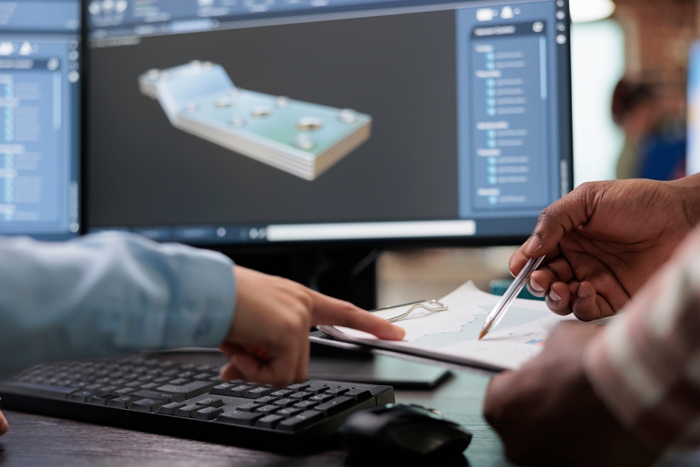
Bespoke PCB CAD design at Newbury Electronics
Fig.1. shows the mechanical detail drawing produced within the PCB CAD project file. It has been constructed around the key component positions, reducing the chance of any mismatch between the position of the component and its corresponding enclosure knockout. The enclosure shown in this image had a base cost of less than £7.00.
In this case, the batch quantity was only 12. A first-off was machined for Newbury to check the mechanical arrangement and after receiving sign-off from our customer, the others were machined as well.
For this project, our client wanted to use a standard off-the-shelf enclosure. However, we also have an in-house capability for sophisticated bespoke mechanical design using Solidworks 3D. This enables us to model, simulate and evaluate complex mechanical designs before proceeding to manufacture.
For small production runs, modifying standard enclosures is more economical.
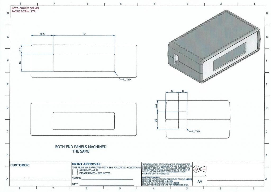
Fig.1.
With this particular project, we were also asked to produce a conformal coating keep-out drawing, as seen in Fig.2. Incidentally, our in-house conformal coating service uses the latest 4-axis CNC spray application technology and UV curing process. Only the zones upon which conformal coating is required are sprayed and no masking off is needed. The process is automated and repeatable, and the finish is exceptionally durable.
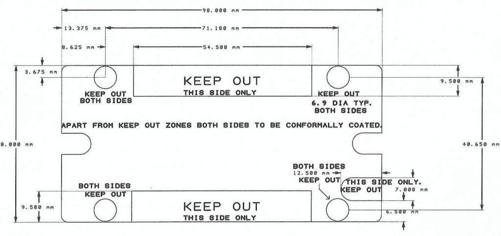
Fig.2.
So, just to recap, the service make-up for this particular project was:-
-
- PCB CAD layout.
- Identifying a suitable enclosure.
- Producing the mechanical arrangement drawings.
- Producing the conformal keep-out drawings.
- Manufacturing the bare PCBs.
- Identifying a suitable enclosure.
- Component procurement.
- PCB and enclosure assembly.
Although this was a small job, bringing together the mechanical processes and matching them to the core PCB CAD layout required the same skills you would need for a project of any size. By integrating the electronic and mechanical design, this project was completed simply and efficiently.
Click to learn more about our PCB CAD layout services at Newbury Electronics. For help with anything else related to PCBs or electronic assembly, please get in touch with us via this contact form. Be sure to contact us for more information about 3D mechanical design.