What quality control
measures are in place for this service?

We are quality approved to ISO9001.

Specialists in Flex PCB Manufacture and Supply

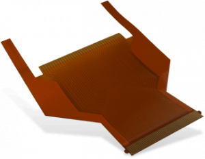
A flexible printed circuit board, otherwise known as a flex circuit or FPCB, is a type of circuit board designed to be bent, folded, or twisted. This flexibility means that they are sometimes preferred over rigid PCBs, with many advantages, including reduced weight, improved heat dissipation, and the ability to fit into tighter spaces, giving them an edge over their more traditional counterparts.

With over 60 years of experience, our professionals can create single sided, double sided (with or without plated through hole technology), multilayered or rigid-flex circuit boards tailored to your needs. We construct flexible circuits through the sequential build-up of flexible component layers, including base polyimide, copper, cover-lay, and stiffeners, bonded by an adhesive layer (epoxy or acrylic), to create the perfect design.

Whichever type of flexible or flexi-rigid PCB you require, our engineers will help you achieve your vision. Our flexible PCBs are available in various turnaround times, depending on the type and volume you require. Send us your specification to receive a free quote today.

What technology and machinery is used?

We use a wide variety of specialist process equipment to manufacture flexible PCBs. These include laser direct imaging, ink-jet printing, flying probe testing, direct metallisation lines, vacuum lamination presses, small hole drilling machines, and integrated strip-etch-strip lines.

Do you still have a question?

Read Our FAQs View our fabrication plant

Get a Quote

Flexible base materials are relatively dimensionally unstable and have to be processed on small step & repeated blanks, typically of a size only 20% of that used for rigid PCBs. This means that flexible PCBs are significantly more expensive to produce than rigid PCBs.

How our flexible circuit service works

We construct flexible circuits via the gradual buildup of component layers. These include a base substrate, a copper layer, a protective coverlay, and stiffeners for improved mechanical support. The bonding between each component layer is provided by an adhesive layer (epoxy or acrylic).

When providing your specification, you should ensure that the materials you select are appropriate for your needs, whether you need a flexible or rigid flex PCB for a static (e.g., one-time bend into a camera) or dynamic (e.g., hard disk drive) application.

If you plan to add electronic components to your board, you must select a base material to withstand solder temperatures, and a stiffener may be added. These are normally applied in the region of the flexible circuit where components are mounted.

Mechanical tooling will also be selected according to the volume and accuracy required. These may be CNC soft tooling (low cost but high unit costs), steel rule (volumes up to a few thousand pieces, medium cost, low dimensional stability), or hard steel punch & die sets (more durable, accurate, & higher cost).

Get a Quote

Who uses our Flexible PCB service?

Flexible and flexi-rigid circuits are typically smaller and lighter than rigid printed circuit boards, which means they are often used to achieve very tight packaging of electronics within smaller enclosures.
Flex circuits’ durable, flexible properties make them well-suited for use in medical devices, industrial equipment, and aerospace and automotive applications. They also have a much longer lifespan than traditional circuit board designs. Our flexible circuits may be assembled as “flat” systems that are folded to fit a smaller enclosure, can also serve as “printed” cable harnesses, and may be used when flexible electrical connections are required.

Why choose Newbury Electronics?

Flexible PCB

Newbury Electronics is a leading UK PCB manufacturer with more than 60 years of experience. We aim to supply high-quality flexible circuits with reliable deliveries, competitive pricing, and excellent technical support. We know that flexible PCBs can be challenging to assemble, but our expertise makes any order a possibility.


Our extensive in-house contract electronic assembly experience allows us to design production pallets for flexible PCBs that optimise assembly efficiency and minimise costs, saving you time and money. Contact our experts for a free flexible printed circuit board quote today.

FAQ's

Our delivery times vary, depending on the type and volume of flexible circuits you choose:

Single Sided

  • Samples 10-15 w/days
  • Production 3-4 weeks

Double Sided

  • Samples 10-15 w/days
  • Production 3-4 weeks

Multi-layers

  • Samples 10-20 w/days
  • Production 4-5 weeks

Rigid-flex

  • Samples 10-25 w/days
  • Production 5-6 weeks

Flexible circuit boards have a range of applications, including:

Computer & peripherals: Notebook computers, LCD monitors, Hard disk drives, Printers, CD-ROMs.
Consumer products: Cameras, Camcorders, Monitors.
Telecommunications: Cellular phones, Wireless phones.
Office equipment: Faxes, Copiers, PDA.
Automobiles: Instrument panels, ABS systems.
Aerospace & military: Satellites, Radar, Missiles, Smart weapons.
Medical instruments: Hearing aids, Heart pacemakers.
Industrial: Motors
Others: Smart cards, Toys.

Copper foil : RA copper 17.5, 35, 70 microns
Copper foil : ED copper 17.5, 35, 70 microns
Base film : Polyimide 17.5, 25, 50 microns
Base film : Polyester 25, 50, 75 microns
Coverlay : Polyimide 25, 50, 75 microns
Coverlay : Polyester 17.5, 35, 70 microns
Coverlay : Solder mask 25, 50 microns
Adhesive : Epoxy 20 – 35 microns
Adhesive : Acrylic 20 – 35 microns
Stiffener : Polymide 25 – 175 microns
Stiffener : Polyester 25 – 300 microns
Stiffener : Glass-epoxy 0.1 – 1.6 mm

  • Minimum track & gap 0.075mm
  • Minimum hole diameter 0.3mm
  • Min total thickness, single sided 80 microns (inc CVL)
  • Min total thickness, double sided 210 microns (inc CVL)
  • Hole diameter tolerance, before plating +/-0.05mm
  • Hole diameter tolerance, after plating +/-0.10mm
  • Outline tolerance (Hard punch tool) +/-0.05mm
  • Pitch Tolerance +/-0.05mm
  • Conductor width tolerance +/-20% of width
  • Maximum economic length of flex circuit 500 mm

The principle manufacturing operations for a double sided flexible circuit are set out below.

  • Cut blanks
  • Drill << CNC drill tool
  • Plate copper (electroless & and electrolytic copper)
  • Laminate and UV print << Photographic tooling
  • Develop
  • Etch
  • Clean
  • Attach coverlays << punched coverlays (2 sides)
  • Hot Lamination
  • Visual inspection << 100% inspection
  • Finished treatment (HASL or Au/Ni)
  • Legend Print
  • Apply stiffener << punched/routed stiffener
  • Punch & die profile << punch tool
  • Electrical test << test fixture
  • Component assembly
  • Electrical test of assembly << test fixture
  • Visual inspect << 100% inspection
  • Pack