How to control impedance
The dielectric constant (Dk) is a measure of the extent that electrostatic flux is concentrated in a given insulating material. It is also known as the relative permittivity (Er). It is a dimensionless ratio of the electrostatic flux concentration exhibited by the material compared with that of a vacuum. In other words, it is the ratio of the capacitance of a given capacitor using the particular insulating material compared with a vacuum insulating material.
Electrical signals travel through copper insulated by a vacuum at the speed of light. These signals are slowed by the ratio of the square root of the Dk of the insulating material. So if the insulator has a Dk of 4, then the signals are slowed by a factor of 2 (being the square root of 4).
In high speed circuitry, the electronic designer must predict the speed of propagation of the electronic signal within the tracking of a printed circuit board when the copper tracks themselves capacitors. The impedance of the transmission line must be controlled to the designed value. This control may be made in a number of ways.
The dielectric material may be changed. Most commonly, FR4 is used as the dielectric since it is the most commonly available low cost substrate. Consequently, the Dk of Fr4 will often be a given in the calculations and other variables must be used.
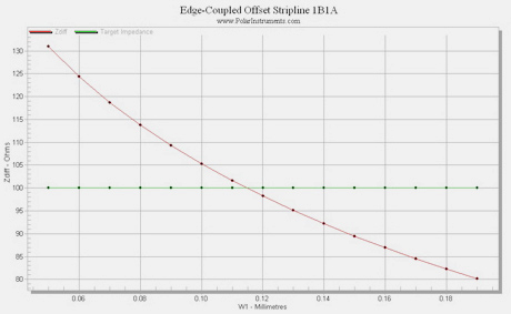
Choosing appropriate geometric configurations of adjacent multiple tracks and ground-planes, varying these track widths and the Z axis gap above the ground-planes are the means by which the designer can achieve the impedance desired.